

Energy-saving retrofit of switched reluctance motor speed control system
The Switched Reluctance Drive (SRD) system comprises a Switched Reluctance Motor (SRM) and an Intelligent SR Controller (ISRD), representing the latest generation of stepless speed control following DC drives and AC variable frequency drives. The motor features a double-salient stator/rotor 12/8 pole structure with concentrated windings on the stator teeth. The rotor, constructed from laminated silicon steel, contains no windings or permanent magnets—only a position sensor. Continuous rotation is achieved by energizing phases in the A-B-C-A sequence; reversing the phase order reverses rotation direction. Retrofitting first addresses the mismatch between the motor's rated power and actual operating load. Existing systems often oversize motors based on peak loads, resulting in prolonged operation at light loads with low efficiency and power factor. SRD utilizes dual closed-loop speed-current control and pulse width modulation to precisely match output torque to actual load, maintaining high efficiency across the entire speed and power range. Second, it resolves starting challenges for heavy-load and high-inertia equipment. SRD delivers a starting torque of 150%~300% of rated torque while drawing only 30% of rated current. In contrast to AC motors requiring 300% current for 100% torque, SRD significantly reduces stress on the power grid and transmission components, offering soft-start capabilities. The controller integrates microcontrollers with digital and analog circuits, ensuring stable operation, strong anti-interference performance, a response time of 0.2 seconds, speed accuracy of ±1.5r/min, and steady-state speed accuracy of 0.15%. It includes comprehensive protection and self-diagnostic functions for overvoltage, undervoltage, phase loss, motor overload, stall, overcurrent, output short circuit, and controller overheating. Status regarding power supply, operation, speed, and protection can be viewed on the display panel. Since the microcontroller program is modifiable, it easily accommodates special user requirements for motor performance. Implementation involves measuring the site equipment load curve and existing motor parameters, then selecting the appropriate model based on four rated speeds (750/1000/1500/3000r/min) and a power range of 0.55~315kW. Installation dimensions are verified against frame sizes 132~355 to achieve 1-for-1 replacement. Following wall-mounted controller installation and parameter tuning, load testing and energy consumption acceptance are performed. Finally, the system connects to a digital IoT motor platform, enabling continuous monitoring of power usage, production capacity, and operational conditions via PC, mobile phones, or tablets. This facilitates immediate detection of idling, frequency reduction, or abnormal shutdowns, providing data support for future energy-saving strategy adjustments.
Use Cases:Oilfield pumping units and well testing machines, injection molding machines and extruders, horizontal boring mills and vertical lathes, screw presses and brick pressing machines, ball mills and crushers, fans and pumps with compressors, etc., under variable load conditions, heavy-load starting, frequent forward/reverse rotation, and frequent start/stop operations.
Solve pain points
Solution Composition
PROCESS
Service Process
- 01
STEP01
Operating condition mapping
- 02
STEP02
Selection Match
- 03
STEP03
Size Compatibility
- 04
STEP04
On-site installation
- 05
STEP05
Parameter Tuning
- 06
STEP06
Commissioning and Acceptance
- 07
STEP07
Data Monitoring
BENEFITS
Plan Benefits
Returns01
Overall efficiency is more than 3% higher than that of AC asynchronous motor VFD systems; at low speeds, it can be over 10% higher. Energy savings typically range from 10% to 50%.
Returns02
Starting torque reaches 150% to 300% of rated torque, while starting current is only 30% of rated current. Heavy-load starting without grid impact.
Returns03
Power factor at both no-load and full-load exceeds 0.98; reactive power compensation is not required.
Returns04
Speed range from 50r/min to rated speed; capable of long-term low-speed operation with temperature rise below rated conditions.
Returns05
Supports frequent forward/reverse rotation and rapid start-stop; four-quadrant operation with constant torque below rated speed and constant power above rated speed.
Returns06
The power converter is connected in series with the motor winding, eliminating the risk of arm-to-arm short-circuit faults. It continues to operate under phase loss and up to 120% overload conditions.
Returns07
The rotor has no windings or permanent magnets, featuring a simple and robust design that withstands harsh environments such as high temperatures and intense vibration.
Returns08
Supports multi-parameter acquisition and digital remote control; integrates with industrial IoT platforms for energy consumption visibility.
Calculation Basis: Energy efficiency grades and efficiency limits are referenced from GB 18613-2020 "Limits of Energy Efficiency and Energy Efficiency Grades for Electric Motors" and IEC 60034-30-1:2014. Product rated efficiency values are sourced from Wolong Electric Drive, JUMO, original product catalogs, and factory test reports. The energy-saving rate range is derived from statistical analysis of actual on-site measurements before and after retrofitting in Panpu's delivered projects under identical operating conditions. Actual performance may vary based on load rate, annual operating hours, and specific operational conditions.
SAME CATEGORY
MotorRecommended Similar Solutions
Also part of the current proposal:MotorCategory:Selection of Permanent Magnet, Magnetic Reluctance, and Standard Motor Replacements for Whole-Plant Energy Retrofitting, for comparison
Motor replacement solutions
Address challenges such as aging equipment, motor maintenance needs, and high procurement costs. Leveraging motor parameters, mechanical dimensions, and actual operating conditions, we provide 1 compatible industrial motor replacement solutions for 1, requiring no structural modifications to your equipment.
View PlanMotor · PM Motor RetrofitPermanent Magnet/Synchronous Reluctance Motor Energy Efficiency Retrofit
Replace traditional induction motors with permanent magnet synchronous motors (PMSM) or permanent magnet reluctance motors (PMRM). Optimize motor-load matching based on operating conditions to reduce energy consumption and improve operational stability.
View PlanMotor · Water ConservationWater utility energy efficiency retrofit
Variable-frequency linked control and permanent magnet motor solution for water supply and sewage treatment, adjusting flow and pressure on demand to reduce energy consumption per ton of water.
View PlanMotor · Building Energy EfficiencyBuilding energy retrofit
Upgrade EC fans and permanent magnet motors in commercial building HVAC systems, integrating with building automation for on-demand cooling and heating.
View PlanRELATED CASES
Recommended Related Cases
Prioritize showcasing retrofit cases from related industries such as rubber tires, with operating conditions closely matching this solution's application scenarios.
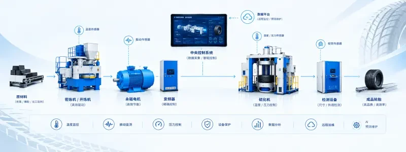
Panpu Permanent Magnet Direct Drive Motor Case: Kiri Chemical Rubber Tire Factory – Whole-Line Drive System Energy Efficiency Retrofit for Tire Production Line
Optimize the motor drive system across the entire tire production line, coordinate multi-device control to reduce overall energy consumption, and adapt to wheel control and molding processes. Help factories achieve energy savings, carbon reduction, and improved production efficiency.
View Cases
Panpu SRM Switched Reluctance Drive System Case Study | Rubber & Plastic Products Factory | Energy-saving Retrofit of Injection Molding Workshop Oil Pumps with Process-Stage Speed Control
The 12 injection molding machines in the rubber and plastic products factory's injection workshop originally used an asynchronous motor + variable pump configuration, resulting in significant energy loss via overflow during the holding pressure and cooling stages. The project has now switched to Panpu SRM switch reluctance motor drive systems for the oil pumps, enabling speed-adjusted oil supply based on process stages.
View Cases
Panpu SRM Switched Reluctance Motor Drive System Case Study | Oilfield Production Zone | Beam Pump Load Speed Regulation and Soft Start Retrofit
In a certain oilfield's production zone, 37 beam pumping units equipped with asynchronous motors have operated under light loads for an extended period, resulting in frequent start-stop cycles and high inrush currents. The project replaced the entire system with Panpu SRM series switched reluctance motor drive systems, enabling speed control based on the pumping unit load curve and soft starting.
View CasesOTHER SOLUTIONS
Other Category Solutions
EC Fan Energy Saving Retrofit
Replace traditional AC fans with EC permanent magnet fans for stepless speed control and on-demand airflow, significantly reducing energy consumption in HVAC and equipment fan systems.
Fan · PANKA EC Fan SolutionPengke EC Fan Air System Energy-Saving Solution
PANKA EC electronic commutation fans replace traditional AC and belt-driven fans. With a direct motor-to-impeller connection, they require zero maintenance and exceed IE5 efficiency standards. They support stepless speed control from 0 to 10V or 4 to 20mA and MODBUS-RTU group control. Paired with FAN Master intelligent selection software for precise model matching based on actual operating conditions, these fans enable energy-efficient retrofits for air systems in HVAC, data centers, and cleanrooms.
Control System · Smart Water IoT MonitoringSmart Monitoring and IoT Operations & Maintenance Solutions for Water and Environmental Protection
Centered on Panpu's electrical control cabinets, SCADA monitoring systems, and self-developed SaaS IoT cloud platform, we integrate process models, intelligent algorithms, BIM visualization, and cloud-based IoT technologies to deliver end-to-end solutions for water and environmental facilities. Our solutions cover terminal data collection, local control, and centralized cloud operations, enabling multi-site aggregation via dedicated VPN networks to a central control center.
Looking for a motor and energy-saving solution tailored to your operating conditions?
Submit request. Our technical engineer will contact you within 1 business days.