
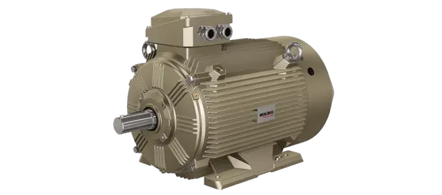
Switched Reluctance Motor
Panbu ElectricPanpu SRM Series Switched Reluctance Motor Speed Control System
The Panpu SRM Series Switched Reluctance Drive (SRD) system comprises a Switched Reluctance Motor (SRM) and an Intelligent Controller (ISRD). As the latest generation of stepless speed control technology following DC drives and AC variable frequency drives, it integrates microelectronics, digital technology, power electronics, and modern electromagnetic design and manufacturing. The motor features a dual- Salient Pole 12/8 structure with concentrated windings on the stator teeth; four adjacent teeth connect to form A, B, and C three-phase windings. The rotor is constructed from laminated silicon steel without windings or permanent magnets, equipped only with a position sensor. Continuous rotation is achieved by energizing phases in the A-B-C-A sequence; reversing the phase order changes the direction. Torque and speed are regulated by controlling current magnitude and switching timing, enabling braking operation. With power switches connected in series with the motor windings, there is no risk of shoot-through short circuits in bridge inverters, ensuring high reliability and simplified protection circuitry. The controller employs a dual closed-loop system for speed and current regulation, utilizing pulse width modulation (PWM) to adjust voltage and current applied to the windings for precise speed control and stability. Built around a microcontroller with digital and analog circuits, it offers stable operation, strong anti-interference capability, and fast response. It includes multiple protection and self-diagnostic functions for overvoltage, undervoltage, phase loss, motor overload, stall, overcurrent, output short circuit, and controller overheating. Status information—including power supply, operation mode, speed, and protection alerts—is displayed on the front panel. Firmware is updatable to meet specific user performance requirements. This system effectively addresses the "over-sized motor for light load" mismatch between rated motor power and actual operating demand, as well as the challenge of high starting torque requirements for heavy-load, high-inertia equipment coupled with low operational efficiency. It is ideal for variable load applications requiring frequent start-stop cycles, such as fans, pumps, lathes, punch presses, mixers, grinders, pumping units, and injection molding machines. The system supports multi-parameter data acquisition and digital remote control, ready for integration into industrial IoT platforms.
Technical Specifications
- Rated Power0.55–31 5kW
- Rated Speed750 / 1000 / 1500 / 3000 RPM
- Speed control range50 r/min to rated speed; capable of continuous low-speed operation
- Rated VoltageAC 110 / 220 / 380 / 660 / 1140V, 50Hz
- Voltage fluctuation tolerance±15%, Frequency tolerance: 50Hz ±10%
- Rated Torque9549 × Rated Power (kW) ÷ Rated Speed (r/min) N·m
- Starting Torque150%~300% of rated torque
- Inrush current30% rated current
- Braking Torque100% Rated Torque
- Overload capacity120% rated power
- Speed Accuracy±1.5 r/min
- Speed stability accuracy0.15% (maximum speed)
- Dynamic Response Time0.2 seconds
- Lift Time0.3–3 seconds, potentiometer calibration
- Jog ControlSwitch or contact, approx. 180 r/min
- Output FeaturesConstant torque below rated speed, constant power above rated speed.
- Power FactorNo-load and full-load both exceed 0.98
- Rated efficiency84.5%~96.5%
- Insulation ClassH-Class (Motor)
- Ingress Protection RatingMotor IP54, Controller IP23
- Work scheduleS1
- Cooling MethodFan self-cooling
- Installation MethodMotor mounted horizontally, controller wall-mounted.
- EnvironmentBelow 1000 meters altitude, vibration below 0.6g
- Ambient TemperatureMotor: 5~40°C; Controller Storage: 25~65°C
- Relative HumidityNot exceeding 90%, no condensation
Key Advantages
High efficiency and excellent energy savings: Overall efficiency across the full speed range and full power output exceeds that of AC asynchronous motor variable frequency drive systems by more than 3%. At low speeds, efficiency can improve by over 10%, with typical energy savings ranging from 10% to 50%.
High starting torque, low starting current: Starting torque exceeds 150% of rated torque; starting current is only 30% of rated current. Ideal for heavy-load starts and applications with frequent load variations.
Soft-start characteristics: Eliminates the inrush current surge of 5 to 7 times rated current typical of standard AC motors, preventing grid disturbances.
Wide speed range: Enables long-term low-speed operation with temperature rise lower than rated conditions, solving the overheating issue of variable frequency drives at low speeds. Maximum speed is not limited by pole count and can be set as needed.
Supports frequent forward/reverse rotation and frequent start/stop cycles. Ideal for applications such as horizontal boring machines, reversible rolling mills, and oilfield pumping units.
High power factor: Both no-load and full-load power factors exceed 0.98, eliminating the need for reactive power compensation devices.
Simple and robust design: rotor has no windings or permanent magnets, enabling straightforward manufacturing and reliable operation in harsh, high-temperature, and high-vibration environments.
Phase loss and overload tolerance: The system continues running with reduced output power during phase loss or single-phase faults. At loads exceeding 120% of rated capacity, speed decreases automatically to prevent motor and controller damage.
High reliability: The power converter is connected in series with the motor windings, eliminating shoot-through faults common in variable frequency drive systems.
Four-quadrant operation: constant torque below rated speed, constant power above rated speed.
Digital Intelligence: Microcomputer-controlled with multi-parameter acquisition and digital remote control; integrates seamlessly with industrial IoT platforms.
Use Cases
General Machinery: Fans, Pumps, Oil Pumps, Compressors
Machine Tools: Gantry Planers, Vertical Lathes, Drilling Machines
Plastic Machinery: Extruders, Injection Molding Machines
Pressure Machinery: Screw Presses, Mechanical Presses, Brick Pressing Machines
Casting Machinery: Shot Blasting Machine
Oilfield Machinery: Vertical Pumping Unit, Beam Pumping Unit, Well Testing Machine
Textile Machinery: Printing Machines, Cloth Winding Machines, Sizing Machines, Looms
Papermaking Machinery: Paper Machine, Calender, Reel
Glass Machinery: Bottle Making Machine
Food Machinery: Mixers, Blenders
Mining & Coal Machinery: Shearer, Roadheader, Ball Mill, Crusher
Metallurgical Machinery: Rolling Mill
Mechanical Upgrades: Elevators, Winches, Hoists, Conveyors
Auxiliary Machinery: Reeling Machine, Uncoiling Machine, Wire架ing Machine
Home Appliances: Washing Machines, Vacuums, Blenders, Food Processors
Vehicles: Electric Cars, Electric Forklifts, Electric Construction Vehicles
Power Generation Equipment: Wind Power
Protection Features
Power Overvoltage
Action value not below 110% rated voltage, manual recovery
Undervoltage
Action value not below 85% rated voltage, manual recovery
Missing Phase
Phase loss shutdown; manual reset required
Motor overload
Delayed 15 second action, manual recovery
Motor stall
Action after 1 second delay, manual recovery
Motor overcurrent
Trip at 160% of rated current, manual reset
Controller output short circuit
Delay 10 seconds to trigger action, manual restore
Controller overheated
Action value is 70°C, manually restored.
Environment and Installation Requirements
- Altitude / Vibration
- Under 1000 meters, below 0.6g
- Storage Temperature
- -25~65℃
- Relative Humidity
- Not exceeding 90%, no condensation
The controller features self-diagnosis. After a protective action, status indicators for power, operation, speed, and protection are displayed on the panel; resume operation manually after following prompts to resolve faults. The microcontroller firmware is upgradable, and protection settings can be customized to suit site conditions.
Selection Parameter Table
← Swipe left or right to view full parameters; first column is fixed
| Project | Parameters |
|---|---|
| Rated Power | 0.55–31 5kW |
| Rated Speed | 750 / 1000 / 1500 / 3000 RPM |
| Speed control range | 50 r/min to rated speed |
| Rated Torque | 9549 × Rated Power (kW) ÷ Rated Speed (r/min) N·m |
| Output Features | Constant torque below rated speed, constant power above rated speed |
| Overload capacity | 120% (rated power) |
| Starting Torque | 150% (rated torque) |
| Braking Torque | 100% (rated torque) |
| Starting current | 30% (rated current) |
| Speed accuracy | ±1.5 r/min |
| Speed stability accuracy | 0.15% (maximum speed) |
| Response time | 0.2 seconds |
| Lift Time | 0.3–3 seconds, potentiometer calibration |
| Jog Control | Switch or contact, approximately 180 r/min |
| Power Voltage/Frequency | 110, 220, 380, 660, 1140V / 50Hz |
| Allowable deviation | Voltage ±15%, Frequency 50Hz±10% |
| Speed setpoint | ≥1kΩ potentiometer; 0~+10V or -10V~+10V voltage |
| Show Features | Power display, motor running status, speed display, protection status |
The above parameters are based on technical documentation for Switched Reluctance Drive (SRD) systems. The motor has a rated voltage of AC 380/660/1140V, insulation class H, duty cycle S1, protection rating IP54, and automatic air cooling. For controllers model CD-160/200 or higher, motors with frame size 355 or larger, and special operating conditions, please contact the Panpu Technology team to confirm specifications. Custom non-standard products can be manufactured according to your requirements.
Download
Panpu SRM Series Switched Reluctance Motor Speed Control SystemProduct Catalog (PDF) – Download for full technical specs, installation dimensions, and selection tables.
Panpu SRM Series Switched Reluctance Motor Speed Control SystemProduct Catalog
PDF Document · Free Public Download
Related Case Studies
All Cases Energy Saving32%
Mining and Metallurgy
Panpu SRM Switched Reluctance Motor Drive System Case Study | Oilfield Production Zone | Beam Pump Load Speed Regulation and Soft Start Retrofit
In a certain oilfield's production zone, 37 beam pumping units equipped with asynchronous motors have operated under light loads for an extended period, resulting in frequent start-stop cycles and high inrush currents. The project replaced the entire system with Panpu SRM series switched reluctance motor drive systems, enabling speed control based on the pumping unit load curve and soft starting.
 Energy Saving28%
Rubber tires
Panpu SRM Switched Reluctance Drive System Case Study | Rubber & Plastic Products Factory | Energy-saving Retrofit of Injection Molding Workshop Oil Pumps with Process-Stage Speed Control
The 12 injection molding machines in the rubber and plastic products factory's injection workshop originally used an asynchronous motor + variable pump configuration, resulting in significant energy loss via overflow during the holding pressure and cooling stages. The project has now switched to Panpu SRM switch reluctance motor drive systems for the oil pumps, enabling speed-adjusted oil supply based on process stages.

Mining and Metallurgy
Wolong High-Voltage Variable Frequency Drive Case Study | Pakistan K Electric Power Supply Project | MV VFD System Tendering and Engineering Delivery
Longde Electric (Zhejiang) Power Electronics issues Authorization Letter NO.WLPEFX20260019, authorizing Pakistani agent Techno Control Pvt. Ltd. to bid for the K Electric VFDs project. The project confirms ten delivery commitments—including technical clarification, drawings, protection coordination, interfaces, HVAC dimensions, foundations, signal exchange, software backup, and O&M training—as specified in the Technical Clarification Letter.
Cases are automatically linked by product series and application industry, allowing you to view retrofit details and performance data for similar operating conditions.
Looking for a motor and energy-saving solution tailored to your operating conditions?
Submit request. Our technical engineer will contact you within 1 business days.